")
Mode Installation Instructions(step 1~step 5)
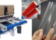
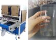
1. Adjust clear cylinder box machine Mold Support Rod
 Press the “Forming Positioning” button to lift the forming positioning plate.
- Checkdistance between the lower forming pressing plate and the upper edge of the mold. If distance is bigger than 2 cm, loosen the screw on the right side of the mold guide rod.
- Press down the mold of clear cylinder box machine and the mold support rod with both hands to make the mold closely adhere to the forming positioning plate. If it is okay, lock the screw.
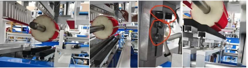
- If the forming baffle still cannot be closely attached to the lower edge of the mold, loosen the two screws at the upper end of the mold support rod.
- Keepto press down the mold with both hands to make the lower edge of the mold closely adhere to the forming positioning plate. Lock the four screws on the mold support rod.
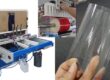
2. clear cylinder box machine Mold main body Installation
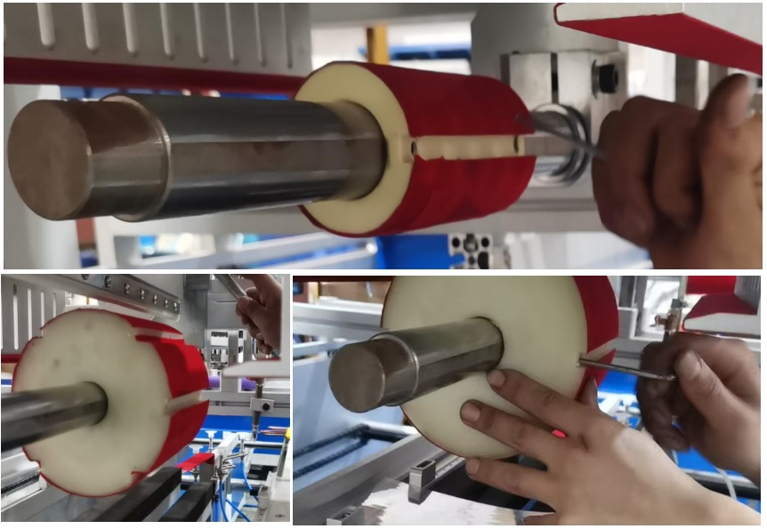 Each mold of clear cylinder box machine has two mold-locking holes equipped with mold-locking set screws.
- Align the mold-locking holes with the flat grooves of the mold support rods and tighten the screws.
- To ensure balanced pressure at two side of the mold, try to install the mold under the forming cylinder.
- Note: The set screws for large molds are relatively long, while those for small molds are relatively short, but they have the same diameter.
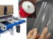
3.Adjustment of the Cylinder Stroke of the Forming Positioning Plate
 Note: When installing the mold, the “Forming Positioning” function has already lifted the forming positioning plate.
- Press the “Forming Positioning” button repeatedly and observe whether the forming positioning plate can slightly lift clear cylinder box machine mold when rising.
- If the mold is lifted too high, turn the cylinder stroke limit tube and the limit nut upward to slightly shorten the upward pressing stroke.
- If the mold is not lifted high enough, turn the cylinder stroke limit tube and the limit nut downward to slightly increase the upward pressing stroke.
- Keep adjusting until when the upper pressing platen for shaping is lifted, you can feel a slight upward vibration by touching the mold guide rod with your hand.
4.Expand the distance of the main guide rod and adjust clamp outward
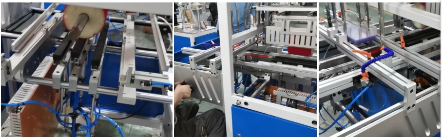 Before adjusting the distance between the upper forming pressing plates, move the main guide rod and sheet feeding guide rod outward to prevent it from obstructing the horizontal movement of the upper forming press plates.
- To move the main guide rod and the sheet feeding guide rod outward, first loosen the screws at the bottom of the clear cylinder box machine main guide rod and the positioning screws of the longitudinal sheet feeding guide rod.
- To move the main guide rod outward, loosen the four positioning screws below the guide rod and then turn the handwheel for the horizontal movement of the main guide rod.
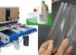
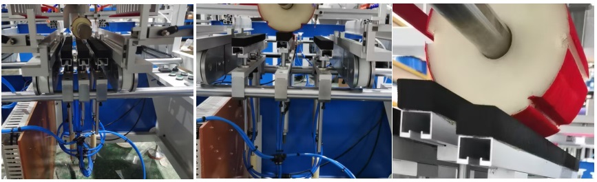
5. Adjustment of the upper forming pressing plate
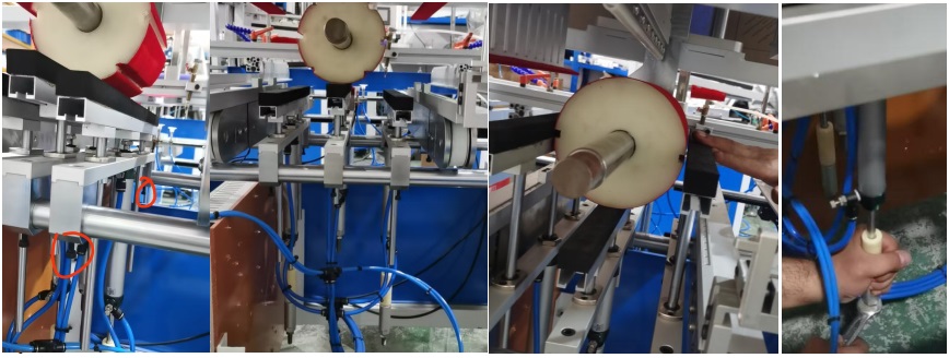 For large molds, the nylon limit tube at the tail end of the white cylinder needs to be removed.
- Ensure that after the upper forming pressing plate is lifted, the upper end of its inner edge is approximately 2 to 6 mm higher than the center line of the mold.
- Move the upper pressing platen horizontally with both hands so that the interval between the inner edge of the upper pressing platen and the corresponding edge of the mold does not exceed 1 mm.
- Lock the positioning screws below the guide rod of the upper forming pressing plateof clear cylinder box machine and the cylinder stroke nut.